What are the options for malleable iron guards or covers to protect malleable iron vs galvanized and operators?

When it comes to protecting malleable iron or galvanized fittings and operators, there are several options for guards or covers that can help prevent accidents, injuries, and damage to the fittings.

Here are some common options:

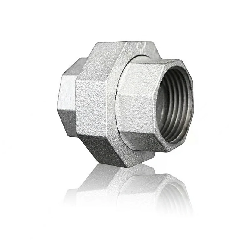
  1. Safety Caps: Safety caps are protective covers designed to fit over the exposed ends of malleable iron or galvanized fittings. These caps provide a barrier to prevent accidental contact with sharp edges or threads, reducing the risk of cuts, abrasions, or injuries to operators.
  2. Plastic or Rubber Guards: Plastic or rubber guards can be installed around malleable iron or galvanized fittings to provide impact protection and cushioning. These guards absorb shocks and vibrations, minimizing the risk of damage to the fittings and reducing the likelihood of injury to operators in case of accidental contact.
  3. Enclosures: Enclosures are protective structures or barriers that surround malleable iron or galvanized fittings to create a physical barrier between the fittings and operators. Enclosures can be made of various materials, such as metal, plastic, or fiberglass, and may include access doors or panels for maintenance and inspection purposes.
  4. Safety Shields: Safety shields are flexible, transparent covers that can be installed around malleable iron or galvanized fittings to protect operators from flying debris, sparks, malleable iron vs galvanized or splashing liquids. These shields provide visibility while offering protection against potential hazards.
  5. Bollard Guards: Bollard guards are sturdy posts or barriers installed around malleable iron or galvanized fittings to prevent accidental impact from vehicles, equipment, or heavy objects. Bollard guards are typically made of steel, concrete, or polymer materials and are anchored securely to the ground to provide effective protection.
  6. Warning Signs and Labels: Clear warning signs and labels should be posted near malleable iron or galvanized fittings to alert operators to potential hazards and remind them to exercise caution. Use internationally recognized safety symbols and text to convey important safety information effectively.
  7. Custom Fabrications: In some cases, custom fabrications may be required to create specialized guards or covers tailored to the specific dimensions and requirements of malleable iron or galvanized fittings. Custom guards can be designed to provide optimal protection while ensuring compatibility with existing equipment and infrastructure.
  8. Barriers or Guardrails: Barriers or guardrails can be installed around malleable iron or galvanized fittings in high-traffic areas or hazardous work zones to prevent unauthorized access and protect operators from accidental contact. These barriers may be permanent or temporary, depending on the application and site requirements.
  9. Personal Protective Equipment (PPE): In addition to guards or covers, operators should also wear appropriate personal protective equipment, such as safety gloves, goggles, helmets, or protective clothing, to minimize the risk of injury while working near malleable iron or galvanized fittings.

By implementing these options for guards or covers, employers can create a safer work environment for operators and protect malleable iron or galvanized fittings from damage or wear caused by accidental contact or impact. It’s essential to assess the specific hazards and requirements of each application and select appropriate protective measures accordingly. Regular inspection and maintenance of guards and covers are also important to ensure their effectiveness over time.

What role do keyways play in gas union fitting installation and alignment?

Keyways play a critical role in gas union fitting installation and alignment by providing a means to secure the fitting to the shaft and maintain proper orientation and alignment between mating components. Here’s how keyways contribute to the installation and alignment process:

  1. Shaft Fixation: Keyways are machined slots or channels cut into the shaft and the inner bore of the gas union fitting. They accommodate a corresponding key, usually a rectangular or square metal piece, which fits snugly into the keyway to prevent rotational movement between the shaft and the fitting. gas union fitting This ensures that the fitting remains securely attached to the shaft during operation.
  2. Alignment: Keyways help ensure proper alignment between the gas union fitting and the shaft by guiding the insertion of the key into the keyway. When the key is correctly positioned in the keyway, it establishes a fixed reference point for aligning the fitting with other components in the assembly, such as adjacent piping or equipment.
  3. Torque Transmission: In addition to preventing rotational movement, keyways facilitate the transmission of torque from the shaft to the gas union fitting or vice versa. As torque is applied to the shaft, the key engages with the keyway, transferring rotational force to the fitting and enabling it to perform its intended function, such as tightening or loosening threaded connections.
  4. Prevention of Slippage: Keyways help prevent slippage or relative movement between the shaft and the gas union fitting, particularly under high loads or torque conditions. By securely locking the two components together, keyways minimize the risk of unintended rotation or disengagement during operation,cast iron bushings which could lead to equipment malfunction or safety hazards.
  5. Maintenance of Positional Accuracy: Keyways maintain positional accuracy and repeatability between the gas union fitting and the shaft, ensuring consistent performance and operational reliability over time. Proper alignment achieved through keyway engagement helps optimize the efficiency and effectiveness of the fitting within the system.
  6. Facilitation of Assembly: During installation or maintenance procedures, keyways simplify the assembly process by guiding the proper insertion and alignment of the gas union fitting onto the shaft. The key serves as a locating feature that helps operators quickly and accurately position the fitting, reducing assembly time and minimizing errors.

Overall, keyways are integral to gas union fitting installation and alignment, providing essential functions such as shaft fixation, alignment guidance, torque transmission, and prevention of slippage. Proper machining and fitting of keyways are crucial to ensuring the reliability, safety, and performance of gas union fittings in gas distribution systems and other applications where precise alignment and secure attachment are paramount.

How do you identify signs of wear or fatigue in grooved fittings during routine inspections?

Identifying signs of wear or fatigue in grooved fittings during routine inspections is crucial for ensuring the integrity and reliability of the piping system.

Here are some common signs to look for:

  1. Visible Damage: Inspect the surface of the grooved fittings for visible signs of damage, such as cracks, dents, gouges, or deformations. Pay close attention to areas where stress concentrations are likely to occur, such as near the grooves or sealing surfaces.
  2. Corrosion: Check for signs of corrosion on the surface of the grooved fittings, particularly in areas exposed to corrosive environments or chemicals. Look for discoloration, pitting, rust formation, or surface irregularities that may indicate corrosion damage.
  3. Worn Grooves: Examine the grooves of the fittings for signs of wear or deformation. Inspect the depth and width of the grooves to ensure they meet the manufacturer’s specifications and have not been excessively worn down due to repeated assembly and disassembly.
  4. Leakage: Monitor the fittings for any signs of leakage, such as visible drips, dampness, or stains around the joints. Leakage may indicate improper assembly, seal failure, or damage to the grooved fitting, requiring further investigation and corrective action.
  5. Loose Fasteners: Check the tightness of fasteners, such as bolts, nuts, or set screws, securing the grooved fittings in place. Loose fasteners can lead to misalignment, vibration, grooved fittings manufacturer and premature wear of the fittings, increasing the risk of failure.
  6. Deformation: Inspect the fittings for any signs of deformation or distortion, particularly in areas subjected to high stress or mechanical loads. Look for signs of bending, twisting, or bowing that may indicate fatigue or overload conditions.
  7. Cracking: Look for any signs of cracking or fracturing in the grooved fittings, particularly in areas where stress concentrations are likely to occur, such as near sharp edges or corners. Cracks may propagate over time and lead to catastrophic failure if left unaddressed.
  8. Seal Condition: Assess the condition of the seals or gaskets used in conjunction with the grooved fittings. Look for signs of wear, compression set, or deterioration that may compromise the sealing integrity and contribute to leakage.
  9. Alignment: Check the alignment of the grooved fittings and adjacent components to ensure proper positioning and fitment. Misalignment can result in uneven loading, stress concentrations, and accelerated wear of the fittings.
  10. Documentation Review: Review maintenance records, inspection reports, and historical data to identify any trends or patterns indicating wear or fatigue-related issues with grooved fittings. Pay attention to any recurring problems or failures that may require corrective action.

If any signs of wear or fatigue are identified during routine inspections, it’s essential to promptly address the issues to prevent further damage, mitigate the risk of failure, and ensure the continued safe operation of the piping system. This may involve replacing worn components, tightening fasteners, adjusting alignment, or implementing preventive maintenance measures to extend the service life of the grooved fittings. Regular inspections and proactive maintenance are key to identifying and addressing potential issues before they escalate into more significant problems.

What measures can be taken to prevent sediment or debris buildup in a double door check valve within a well valve system?

Preventing sediment or debris buildup in a double door check valve within a well valve system is essential to maintain its functionality and prevent blockages.

Here are several measures that can be taken to achieve this:

  1. Regular Inspection and Cleaning: Implement a schedule for regular inspection and cleaning of the double door check valve. This involves visually inspecting the valve for any signs of sediment or debris accumulation and cleaning it as needed to prevent buildup.
  2. Install Sediment Filters: Install sediment filters upstream of the double door check valve to trap particles and prevent them from entering the valve. These filters can help reduce the amount of sediment and debris that reaches the valve, thereby minimizing buildup.
  3. Flush the System: Periodically flush the well valve system to remove any accumulated sediment or debris. Flushing involves temporarily increasing the flow rate through the system to dislodge and remove particles that may be clinging to the valve or piping.
  4. Use Strainers or Screens: Install strainers or screens on the inlet side of the double door check valve to capture large debris particles before they can enter the valve. These devices can help prevent blockages and reduce the risk of sediment buildup.
  5. Implement Sedimentation Tanks: Install sedimentation tanks or settling basins upstream of the well valve system to allow suspended solids to settle out before reaching the valve.double door check valve This can significantly reduce the amount of sediment and debris that enters the valve and prolong its lifespan.
  6. Maintain Proper Flow Velocity: Ensure that the flow velocity through the well valve system is sufficient to prevent sedimentation and settling of particles. Adequate flow velocity helps keep sediment and debris in suspension, preventing them from accumulating in the valve.
  7. Monitor Water Quality: Regularly monitor the quality of water entering the well valve system for signs of sediment or debris contamination. Address any issues with water quality promptly to prevent buildup in the double door check valve.
  8. Proper Installation: Ensure that the double door check valve is installed correctly according to manufacturer guidelines. Proper installation can help optimize the performance of the valve and minimize the risk of sediment or debris accumulation.
  9. Consider Alternative Valve Types: Depending on the specific requirements of the well valve system, consider using alternative valve types that are less prone to sediment or debris buildup, such as ball valves or diaphragm valves.

By implementing these measures, it’s possible to minimize sediment or debris buildup in a double door check valve within a well valve system, ensuring smooth operation and reducing the risk of blockages or malfunctions. Regular maintenance and proactive measures are key to preserving the integrity and efficiency of the valve.

What role does a ball valves play in preventing system leaks in a well valves setup?

Ball valves play a crucial role in preventing system leaks in a well valve setup due to their robust design and sealing mechanism.

Here’s how they contribute to leak prevention:

  1. Tight Seal: Ball valves feature a spherical closure mechanism (the ball) with a hole through its center. When the valve is in the closed position, the ball is rotated perpendicular to the flow, blocking the passage of fluid completely. This tight seal effectively prevents any leakage through the valve, ensuring the integrity of the system.
  2. Durable Sealing Materials: The sealing mechanism of ball valves typically involves resilient materials such as Teflon (PTFE) or other elastomers. These materials provide excellent sealing properties, even under high pressure or temperature conditions commonly encountered in well systems. They form a tight seal against the valve body and the ball, preventing any fluid from escaping.
  3. Minimal Wear and Tear: Ball valves have few moving parts, reducing the risk of wear and tear over time. The smooth, spherical surface of the ball minimizes friction during operation,china ball valves preserving the integrity of the sealing surfaces. As a result, ball valves maintain their sealing effectiveness for an extended period, minimizing the likelihood of leaks in the well valve setup.
  4. Bi-Directional Sealing: Ball valves offer bi-directional sealing, meaning they can effectively block fluid flow in both directions. This feature is crucial in well systems where fluid flow might reverse due to changes in pressure or other factors. The ability to seal in either direction ensures comprehensive leak prevention under varying operating conditions.
  5. Positive Shut-Off: Ball valves provide positive shut-off, meaning they completely isolate the flow when closed without any residual leakage. This characteristic is essential for maintaining system integrity and preventing leaks, particularly in critical applications such as well systems where any leakage can lead to water loss, contamination, or other undesirable consequences.
  6. High Pressure and Temperature Resistance: Ball valves are designed to withstand high pressure and temperature conditions commonly encountered in well systems. The robust construction and materials used in ball valve manufacturing ensure reliable performance even in demanding environments, reducing the risk of valve failure and associated leaks.
  7. Ease of Maintenance: While ball valves require minimal maintenance due to their durable design, they are also relatively easy to inspect and service when necessary. This ease of maintenance allows for proactive measures to be taken, such as replacing worn seals or components, to ensure continued leak prevention in the well valve setup.

Overall, ball valves serve as reliable barriers against system leaks in well valve setups by offering tight sealing, durability, minimal wear and tear, bi-directional sealing, positive shut-off, high pressure and temperature resistance, and ease of maintenance. Their robust design and sealing mechanism make them indispensable components for ensuring the integrity and efficiency of well systems.

How does a ball valve contribute to the smooth operation of a well valve during varying flow rates?

Ball valves contribute to the smooth operation of a well valve during varying flow rates primarily due to their design characteristics and operational flexibility. Here’s how they achieve this:

  1. Quick Response: Ball valves are known for their rapid response to changes in flow rates. When the valve is partially open, the ball can be quickly rotated to adjust the flow rate, allowing for precise control over the fluid passing through the valve. This quick response capability ensures smooth operation even during sudden changes in flow conditions.
  2. Linear Flow Control: Ball valves offer linear flow characteristics, meaning the flow rate through the valve is directly proportional to the degree of valve opening. As the ball is rotated, the flow area gradually increases or decreases, resulting in a linear relationship between the valve position and the flow rate. This linear control enables smooth and predictable flow modulation across varying flow rates in the well system.
  3. Minimal Turbulence: The streamlined flow path provided by the spherical design of the ball minimizes turbulence within the valve, particularly when the valve is partially open. ball valve china This reduction in turbulence helps maintain a stable flow profile and prevents flow disturbances or pressure fluctuations, contributing to smoother operation of the well valve, especially at varying flow rates.
  4. Low Pressure Drop: Ball valves typically have low pressure drop characteristics, meaning they cause minimal resistance to flow when fully open. This feature allows for efficient fluid transfer through the valve, even at high flow rates, without significant energy losses or pressure fluctuations. The low pressure drop facilitates smooth operation across a wide range of flow rates in the well system.
  5. Bi-Directional Flow: Ball valves can accommodate bi-directional flow, meaning they can control fluid flow in both directions with equal effectiveness. This bi-directional capability ensures consistent performance and smooth operation, regardless of the flow direction within the well system. It allows for seamless transition between different operating conditions without compromising flow control.
  6. Robust Construction: Ball valves are constructed with durable materials such as stainless steel, brass, or PVC, ensuring reliability and longevity in demanding well system environments. The robust construction enables the valve to withstand varying flow rates, pressure fluctuations, and other operational challenges while maintaining smooth operation over time.
  7. Minimal Maintenance Requirements: Ball valves have fewer moving parts compared to other valve types, resulting in lower maintenance requirements. With proper installation and periodic inspection, ball valves can continue to operate smoothly across varying flow rates without the need for frequent adjustments or repairs, contributing to overall system reliability and efficiency.

In summary, ball valves facilitate smooth operation in well valve systems during varying flow rates through their quick response, linear flow control, minimal turbulence, low pressure drop, bi-directional flow capability, robust construction, and minimal maintenance requirements. These characteristics make ball valves well-suited for maintaining consistent and reliable flow control in dynamic well system environments.

What role do undercarriage of excavator play in reducing vibration and noise during excavator operation?

The undercarriage of an excavator plays a significant role in reducing vibration and noise during excavator operation through several mechanisms:

  1. Shock Absorption: Undercarriage components, such as track rollers, idlers, and track chains, are designed to absorb shocks and vibrations generated by the movement of the excavator over rough terrain. The flexibility and damping properties of these components help dissipate energy and reduce the transmission of vibrations to the rest of the machine, resulting in a smoother and quieter ride for the operator.
  2. Isolation of Vibrations: The undercarriage acts as a buffer between the tracks and the main structure of the excavator, isolating vibrations generated by the tracks from the cab and other critical components. By minimizing the transfer of vibrations, the undercarriage helps reduce noise levels inside the operator’s cab, enhancing operator comfort and reducing fatigue during extended periods of operation.
  3. Dampening Impact Forces: As the excavator performs various digging, lifting, and loading tasks, it generates impact forces that can propagate through the undercarriage and into the ground. Well-designed undercarriage components absorb and dampen these impact forces, minimizing the reverberation of noise and vibration back into the machine and surrounding environment.
  4. Balancing Load Distribution: Properly tensioned and aligned undercarriage components help distribute the weight of the excavator evenly across the tracks, undercarriage of excavator minimizing track slippage and excessive ground pressure. This balanced load distribution reduces the need for aggressive machine movements and mitigates the generation of noise and vibration associated with sudden accelerations, decelerations, and directional changes.
  5. Effective Lubrication Systems: Undercarriage components rely on lubrication to reduce friction and wear, ensuring smooth operation and minimizing noise generation. Well-maintained lubrication systems, including centralized greasing points and automatic lubrication systems, ensure that undercarriage components remain properly lubricated, reducing friction-related noise and vibration during operation.
  6. Vibration Isolation Mounts: Some excavators are equipped with vibration isolation mounts or suspension systems that further dampen vibrations transmitted from the undercarriage to the chassis and operator’s cab. These mounts absorb and dissipate vibrations, providing additional comfort for the operator and reducing noise levels within the cab.
  7. Sound-Dampening Materials: Modern excavators may incorporate sound-dampening materials within the undercarriage structure and cab interior to further reduce noise levels. These materials absorb and block airborne sound waves, minimizing noise transmission and creating a quieter operating environment for the operator and nearby personnel.

Overall, the undercarriage of an excavator plays a crucial role in reducing vibration and noise during excavator operation by absorbing shocks, isolating vibrations, dampening impact forces, balancing load distribution, maintaining effective lubrication, utilizing vibration isolation mounts, and incorporating sound-dampening materials. These features contribute to a more comfortable and productive working environment for operators and help minimize the impact of excavator operation on surrounding areas and personnel.

How do parts of excavator contribute to the efficiency of excavator hydraulic systems?

Various parts of an excavator contribute to the efficiency of its hydraulic systems in different ways:

  1. Hydraulic Cylinders: Hydraulic cylinders are responsible for converting hydraulic fluid pressure into linear mechanical force and motion. They play a crucial role in controlling the movement of the excavator’s boom, arm, and bucket. Efficient hydraulic cylinders with properly sealed pistons and minimal internal leakage ensure smooth and precise operation, maximizing the efficiency of hydraulic system energy transfer.
  2. Hydraulic Pump: The hydraulic pump is the heart of the excavator’s hydraulic system, providing the necessary hydraulic pressure to power various hydraulic functions. Modern excavators often use variable displacement pumps that adjust their output based on the demand from hydraulic actuators. Efficient hydraulic pumps minimize energy losses and deliver the required hydraulic power precisely when needed, improving overall system efficiency.
  3. Control Valves: Control valves regulate the flow and direction of hydraulic fluid within the excavator’s hydraulic system. They control the operation of hydraulic cylinders and other hydraulic actuators, allowing the operator to manipulate the machine’s movements. Efficient control valves with low pressure drops and precise flow control optimize hydraulic system performance, reducing energy consumption and improving response times.
  4. Hydraulic Filters: Hydraulic filters remove contaminants such as dirt, debris, and particulate matter from the hydraulic fluid, ensuring clean and reliable operation of hydraulic components. Clean hydraulic fluid reduces friction and wear on hydraulic system components, improving efficiency and extending the lifespan of hydraulic pumps,parts of excavator valves, and cylinders.
  5. Hydraulic Lines and Fittings: Hydraulic lines and fittings transport hydraulic fluid between various components of the excavator’s hydraulic system. Efficiently designed hydraulic lines with proper sizing, routing, and insulation minimize pressure drops and fluid friction losses, improving overall system efficiency and responsiveness.
  6. Hydraulic Reservoir: The hydraulic reservoir stores hydraulic fluid and helps dissipate heat generated during operation. Properly sized and designed hydraulic reservoirs maintain hydraulic fluid at optimal operating temperatures, preventing overheating and degradation of hydraulic fluid properties, which can reduce system efficiency.
  7. Hydraulic Fluid: The choice of hydraulic fluid also plays a significant role in hydraulic system efficiency. High-quality hydraulic fluids with the appropriate viscosity, additives, and thermal stability properties ensure smooth operation and protect hydraulic components from wear and corrosion. Regular maintenance of hydraulic fluid, including proper monitoring, filtration, and replacement, helps maintain hydraulic system efficiency over time.
  8. Efficient System Design: The overall design of the excavator’s hydraulic system, including component layout, circuit design, and system integration, influences system efficiency. Well-designed hydraulic systems minimize pressure losses, optimize flow distribution, and match hydraulic component capacities to actual machine requirements, maximizing overall system efficiency and performance.

By ensuring that these various components are well-designed, properly maintained, and effectively integrated into the excavator’s hydraulic system, operators can maximize the efficiency and performance of their machines, leading to improved productivity, reduced fuel consumption, and lower operating costs over the machine’s lifespan.

How does kraft tube lip balm contribute to a comfortable and lightweight feel on the lips?

Kraft tube lip balm contributes to a comfortable and lightweight feel on the lips through a combination of factors related to its formulation, packaging, and the choice of ingredients.

Here are several ways in which kraft tube lip balm achieves a comfortable and lightweight experience:

  1. Lightweight Formulation: Kraft tube lip balms are often formulated with lightweight ingredients that provide a smooth and easily spreadable texture. This ensures that the product feels light on the lips without a heavy or greasy sensation.
  2. Balanced Blend of Ingredients: Lip balm formulations for kraft tubes typically include a balanced blend of moisturizing agents, emollients, and natural oils. These ingredients work together to deliver effective hydration to the lips without adding unnecessary weight.
  3. Absence of Heavy Waxes: Some lip balms use heavy waxes that can feel thick and sticky on the lips. Kraft tube lip balms are designed to avoid the use of excessive waxes, contributing to a more lightweight and comfortable application.
  4. Quick Absorption: The formulation of kraft tube lip balms is often designed for quick absorption into the lips. This ensures that the product is absorbed efficiently, leaving a thin, comfortable layer that does not feel heavy or cumbersome.
  5. Smooth Application: Kraft tube lip balms have a smooth and glide-on application, facilitating easy and even coverage. The smooth application contributes to a comfortable feel on the lips, and the product spreads evenly without clumping or dragging.
  6. Non-Greasy Finish: Lip balms in kraft tubes are formulated to provide a non-greasy finish. This means that the product absorbs well into the lips, leaving them moisturized without leaving a heavy or oily residue.
  7. Natural and Organic Ingredients: Many kraft tube lip balms feature natural and organic ingredients that are lightweight and compatible with the skin. These ingredients contribute to a comfortable and gentle feel on the lips.
  8. Minimized Friction: The formulation helps minimize friction during application. kraft tube lip balm This reduces any potential discomfort or drag on the lips, ensuring that the lip balm glides smoothly for a more pleasant experience.
  9. Breathable Formulation: Kraft tube lip balms allow the skin on the lips to breathe while providing essential moisture. This breathable formulation adds to the overall comfort and lightweight feel of the product.
  10. Adaptability to Different Environments: Whether in warm or cold environments, kraft tube lip balms are designed to adapt to various conditions. They remain comfortable on the lips without feeling too heavy or melting excessively in warmer temperatures.
  11. Versatility in Use: Kraft tube lip balms are versatile and suitable for various occasions. They can be worn alone for a lightweight, natural look or layered under lipstick for added hydration without compromising the weight or comfort of the lip product.
  12. Minimalist Packaging: The kraft tube packaging itself is often minimalist and lightweight. The design ensures that the overall product is easy to carry, making it convenient for on-the-go use without adding unnecessary weight to a bag or pocket.

In summary, kraft tube lip balm achieves a comfortable and lightweight feel on the lips through a thoughtfully crafted formulation that emphasizes quick absorption, a smooth application, and the use of lightweight ingredients. This contributes to an enjoyable user experience and promotes the natural comfort of the lips.

How does lip oil contribute to a natural and dewy lip finish?

Lip oil contributes to a natural and dewy lip finish through its unique formulation, which combines hydrating and nourishing ingredients with a lightweight and glossy texture.

Here are several ways in which lip oil achieves a natural and dewy lip appearance:

  1. Sheer Tint or Clear Formulation: Many lip oils come in a sheer tint or clear formulation. This allows the natural color of the lips to shine through while enhancing their appearance with a subtle hint of color or a glossy finish, contributing to a natural look.
  2. High-Shine Finish: Lip oils are known for their high-shine finish. The glossy effect adds a luminous quality to the lips, creating a dewy appearance that mimics the natural sheen of well-moisturized and healthy lips.
  3. Hydration and Moisture: Lip oils are formulated with hydrating ingredients, such as natural oils (e.g., jojoba oil, coconut oil) and moisturizing agents. These components deeply hydrate the lips, giving them a plump and dewy look by addressing dryness and preventing a matte or flat appearance.
  4. Reflective Properties: Some lip oils contain reflective particles or micro-shimmer that catch and reflect light. This creates a luminous effect on the lips, enhancing their natural beauty and contributing to a dewy finish.
  5. Smooth Texture: Lip oils have a smooth and lightweight texture that glides effortlessly on the lips. This smooth application contributes to an even distribution of the product, ensuring that the lips appear naturally dewy without any clumping or unevenness.
  6. Non-Sticky Feel: Unlike some traditional lip glosses, lip oils are often formulated to provide a non-sticky feel. This ensures that the lips feel comfortable and look naturally dewy without the tackiness commonly associated with glossier products.
  7. Emollient and Softening Effect: Lip oils have emollient properties that soften the texture of the lips. lip oil wholesale This softening effect contributes to a natural appearance by smoothing out any roughness or dry patches, creating a dewy and supple finish.
  8. Enhancement of Lip Texture: The nourishing ingredients in lip oils work to improve the overall texture of the lips. By providing essential nutrients, lip oils contribute to a healthy and smooth lip surface, enhancing the natural appearance of the lips.
  9. Customizable Application: Lip oils often allow for customizable application. Users can apply a sheer layer for a subtle dewy effect or layer the product for a more intense shine, providing flexibility in achieving the desired level of dewiness.
  10. Compatibility with Bare Lips or Over Lipstick: Lip oils can be applied directly to bare lips for a natural and dewy look. Additionally, they can be layered over lipstick or lip liner to add a glossy finish without compromising the underlying color, offering versatility in achieving different lip effects.
  11. Long-Lasting Hydration: Lip oils typically provide long-lasting hydration. This ensures that the lips remain moisturized throughout the day, contributing to a dewy finish that doesn’t fade quickly.

In summary, lip oil achieves a natural and dewy lip finish by combining hydrating properties, high-shine effects, reflective particles, and a non-sticky feel. The result is a luscious and luminous appearance that enhances the natural beauty of the lips while providing long-lasting hydration and comfort.

How is the sanitary napkin production line designed to handle different types of raw material rolls?

The sanitary napkin production line is designed to handle different types of raw material rolls, ensuring flexibility and adaptability in the manufacturing process.

Here’s how the production line is typically designed to accommodate various types of raw material rolls:

  1. Roll Compatibility:
    • The production line is engineered to accommodate rolls of different widths, diameters, and core sizes. This versatility allows for the use of various raw material rolls based on the specific requirements of the sanitary napkin being produced.
  2. Adjustable Unwinding Mechanism:
    • An adjustable unwinding mechanism is incorporated into the production line. This mechanism can be customized to handle rolls of different dimensions by allowing for adjustments in tension, speed, and alignment.
  3. Tension Control Systems:
    • Tension control systems are implemented to ensure uniform tension across the raw material as it unwinds from the rolls. This is crucial for maintaining consistency in the manufacturing process, regardless of the type of raw material being used.
  4. Roll Loading and Unloading Stations:
    • The production line is equipped with loading and unloading stations designed to handle different roll sizes. Quick-change systems may be implemented to streamline the process of switching between rolls during production changeovers.
  5. Web Guide Systems:
    • Web guide systems are employed to align and guide the raw material as it moves through the production line. China sanitary napkin production line suppliers These systems can be adjusted to accommodate variations in material width, preventing misalignment issues.
  6. Material Splicing Mechanisms:
    • In cases where rolls need to be changed during production, material splicing mechanisms are integrated to seamlessly transition from one roll to another. This minimizes downtime and ensures continuous operation.
  7. Automatic Tension Adjustment:
    • Some advanced production lines feature automatic tension adjustment systems. These systems use sensors to monitor the tension in the material and make real-time adjustments to maintain optimal tension levels, irrespective of the raw material roll type.
  8. Material Quality Sensors:
    • Sensors may be installed to assess the quality of the incoming raw material. These sensors can detect variations in thickness, texture, or other properties, allowing the production line to make necessary adjustments for different material types.
  9. Customizable Cutting Mechanisms:
    • The cutting mechanisms in the production line are designed to be customizable, accommodating variations in material thickness and width. This ensures precise cutting and shaping of the sanitary napkins.
  10. Feeding Systems for Different Layers:
    • For multi-layered sanitary napkins, the production line includes feeding systems for different layers of materials. These systems can handle various materials simultaneously, allowing for the assembly of multi-component napkins.
  11. Material Inspection Stations:
    • Inspection stations equipped with cameras and sensors are strategically placed along the production line to monitor the quality of the raw materials. Any deviations or defects are detected early in the process, enabling corrective actions.
  12. User Interface for Settings:
    • The production line is equipped with a user interface that allows operators to input specific settings based on the characteristics of the raw materials being used. This interface simplifies the adjustment process during material changes.

By incorporating these features, the sanitary napkin production line is designed to be versatile and adaptable, capable of handling different types of raw material rolls to meet diverse product specifications and market demands.

How does the machine handle the integration of wetness indicators in baby pants production line?

The integration of wetness indicators in baby pants production involves incorporating a feature that visually signals when the diaper is wet.

Here’s a general overview of how the machine handles the integration of wetness indicators in a baby pants production line:

  1. Material Selection:
    • Choose materials that are compatible with wetness indicators. The wetness indicator is typically a color-changing material that reacts to moisture. This material is often placed in a specific area of the diaper.
  2. Positioning in the Design:
    • Determine the location in the diaper design where the wetness indicator will be placed. This is often in the diaper’s core, close to the absorbent materials.
  3. Feeding and Integration:
    • Integrate the wetness indicator material into the production line’s material feeding system. This may involve a separate feeding mechanism or station dedicated to adding the wetness indicator to the diapers.
  4. Cutting and Shaping:
    • Coordinate the cutting and shaping process to ensure that the wetness indicator is appropriately positioned within each diaper. Precision is crucial to maintain accuracy in signaling wetness.
  5. Bonding Technology:
    • Use bonding technologies, such as ultrasonic bonding or adhesive application,baby pants production line manufacturers to secure the wetness indicator in place. The bonding process ensures that the indicator remains attached to the diaper throughout its use.
  6. Quality Control and Inspection:
    • Implement quality control measures to inspect each diaper for the correct placement and attachment of the wetness indicator. Automated inspection systems may be employed to identify any deviations from the specified standards.
  7. Adjustable Systems:
    • Design the production line with adjustable systems to accommodate variations in the size and positioning of the wetness indicator based on diaper specifications.
  8. Testing for Responsiveness:
    • Conduct testing to ensure the responsiveness of the wetness indicator. This may involve simulated wetting or exposure to moisture to verify that the color-changing reaction occurs as intended.
  9. Integration with Packaging:
    • Coordinate the integration of wetness indicators with the packaging process. This includes aligning the indicator’s position with the packaging design and ensuring that it remains visible to caregivers.
  10. Consistency in Production:
    • Implement measures to ensure consistency in the production of diapers with wetness indicators. This includes monitoring and controlling factors such as material thickness and machine settings.
  11. User-Friendly Design:
    • Consider user experience in the design of the wetness indicator. Ensure that it is positioned in a way that is easily visible to caregivers and provides a clear indication of wetness.
  12. Automation for Efficiency:
    • Explore automation options for the integration of wetness indicators to enhance efficiency and reduce the likelihood of errors in the production process.

By carefully incorporating wetness indicators into the baby pants production line with attention to precision, quality control, and user-friendliness, manufacturers can provide a valuable feature for caregivers while maintaining the overall integrity of the diaper.